Getting started
Welcome to the 640 board - this guide will describe all the features of the 640 board and show you how to control up to 6 motors or 3 stepper motors and 2 servos very simply.
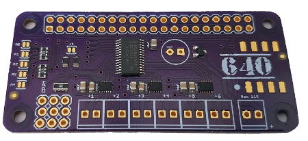
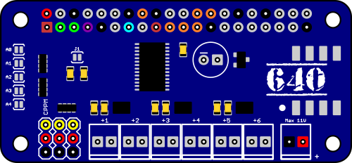
Board layout
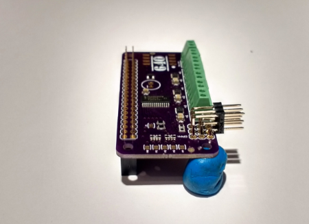
Before we start to assemble your board, we’ll take a look at what each section is and what it is for. Place your 640 board on a table in front of you and identify each area.
CPPM / PPM-SUM
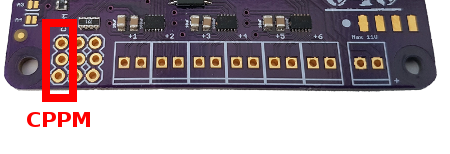
This is the connection that allows you connect a Radio Control (RC) receiver so that you can extend the range of control for your robot.
Servos
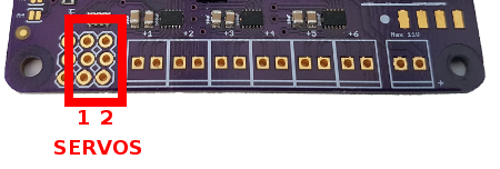
The 640 board has connections for two Servos. They default to being powered by the Raspberry Pi 5v supply, but we can switch them to be powered by the external battery supply if we want to.
Motors
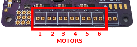
The 640 board can control 6 independent motors. Each motor has a connection with two pins (or terminals if you are using the screw terminal connections). It doesn’t matter which way around you wire your motor, just make sure that you wire them all the same way. If you find that sending a Forward command makes your robot go backwards, then you can switch the wires around.
Power
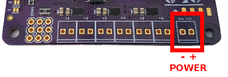
The power connection can accept from 2v all the way up to 11v DC - the power you connect here is isolated from your Raspberry Pi and only goes to the motors. Make sure you match your recommended motor voltage as too much power can damage them, and too little won’t make them turn.
Expansion area
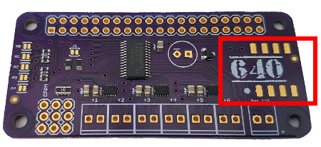
This area to the right of the board is for adding extra expansion boards to increase the functionality available to you. For more information on adding expansion boards look here
Address selection
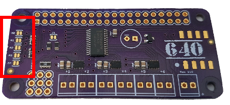
The 640 board uses I2C to control the motors. You can have a lot of I2C controlled boards on your Raspberry Pi at the same time, but each must have a unique address.
We have set up the 640 board to use the address 0x60. If you find that this conflicts with another board you want to use, and you can’t change the address of that board, then you can use these 5 solder jumpers to change the 640 board address.
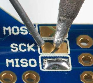
How to change the address
Each of the address pins (A0 - A4) can be set to 0 (un-soldered) or 1 (soldered). You set an address pin to 1 by adding solder to each pad of the address pin until the two parts join.
Each address jumper has a binary value - A0 = 1, A1 = 2, A3 = 4, A4 = 8
The starting address for the 640 board is 0x60 - if we solder jumper A0 then the address will be 0x60 + 1 = 0x61. Soldering A0 and A1 will give us 0x60 + 1 + 2 = 0x63
Setup your 640
Now that we know what each part of the board is for, it’s time to solder all the connections - it doesn’t matter what order you attach the connections to your board, but we’ve found that the order below is the simplest.
Assemble the parts
IMPORTANT - if you have an expansion board that you want to add to your 640 board, then you should add that first as it will be a lot easier than adding it after soldering connectors to the board.
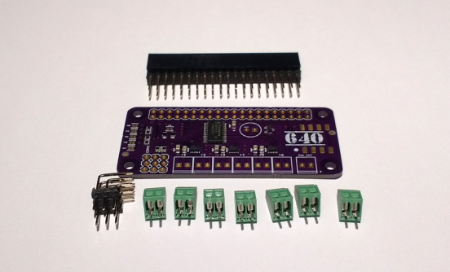
As we don’t know what headers and connectors you selected when you ordered your 640 board - we’re going to show you how to connect the most common selection - other connectors and headers should attach in the same way.
Hint - A lump of plasticine or clay is very useful to hold your board level.
Attach the 3 pin servo header
The first part to slot into place is the 3 x 3 connector for the CPPM and Servos. The holes for this part are aligned so that the connector should fit tightly and be held in place.
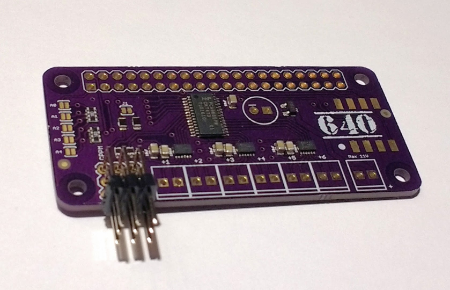
Slot it in place, but don’t solder it yet.
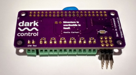
Attach the motor and power terminals
Now we need to add the motor and power connectors - slot each in place making sure that you have them the right way around (for the screw terminals the holes should be at the front of the board).
Use a piece of paper or card to hold the connectors in place and turn the board upside down. Slide the paper out from under the board and use a piece of plasticine to prop the board up level.
Make sure everything is lined up correctly - use extra plasticine to align connectors if needed. Once you are happy, solder each of the pins.
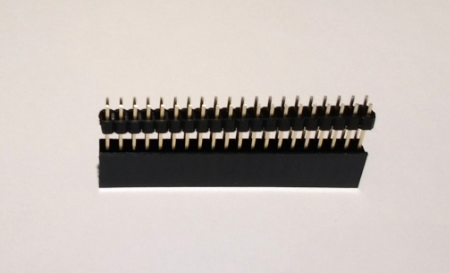
Attach the header
For this example we’ll show you how to connect a stackable header, as it’s the most complex.
Due to the length of the stackable headers pins, it can sometimes be a hassle to get them through the holes on the board.
We’ve found that if you slide up the spacer on the stackable header so that it is near the top, you can get the pins into the boards header holes a lot easier and then slide the spacer back down again.
Once you have your header in place, use some plasticine to make sure the board is level and then solder away. You should solder a single pin first, then make sure the header is level - if it isn’t then apply the soldering iron to the pin again and move the header until it is correct.
Now that your board is set up, it’s time to configure your Raspberry Pi so that you can use it.
Setting up your Pi
Before we can start using the 640 board we need to enable the interfaces that the board uses on your Raspberry Pi.
The 640 board is controlled using the I2C interface. Any expansion boards attached to your 640 board are controlled using the SPI interface.
Enable I2C and SPI in Pixel
If you are using the graphical interface on your Raspberry Pi then click on your main menu icon, move down to Preferences and click on the Raspberry Pi Configuration menu item. Once open click on the Interfaces tab and you should see something like in the image below.
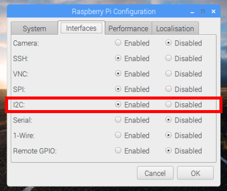
Make sure that the line labelled I2C is set to enabled.
If you have an expansion board then you’ll need to enable the SPI interface as well on the line above, so click the Enabled setting next to the SPI label
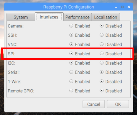
Once you click Ok you may be promtped to reboot your Raspberry Pi - go ahead and reboot.
Enable I2C and SPI on the command line
If you are only using the command line on your Raspberry Pi then you will need to use the text version of the Raspberry Pi configuration tool to enable the interfaces.
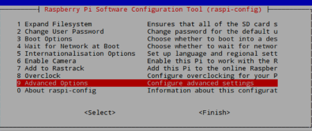
Type the following to bring up the configuration interface:
$ sudo raspi-configOnce the menu is showing, scroll down to the Advanced Options menu and press Enter.
Now we’ll need to enable the I2C interface, so move down I2C menu and press Enter. You’ll be asked if you want to enabled I2C - select Yes and you will see a confirmation and be returned to the main menu.
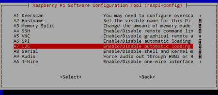
Go to the Advanced Options again and do the same for SPI
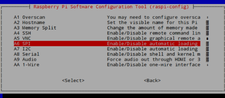
This time when you are returned to the main menu, move down to the Finish option (pressing the right arrow key twice will get you there) and press enter.
You have now enabled the interfaces you need to use your board.
Reboot your Pi
Once you have enabled the interfaces you will need to reboot your Raspberry Pi so that the required libraries can be loaded. This is an important step and your code won’t run correctly without it.
Wiring up the 640 board
Now that we have your 640 board and Raspberry Pi setup, it’s time to connect some motors and servos to it.
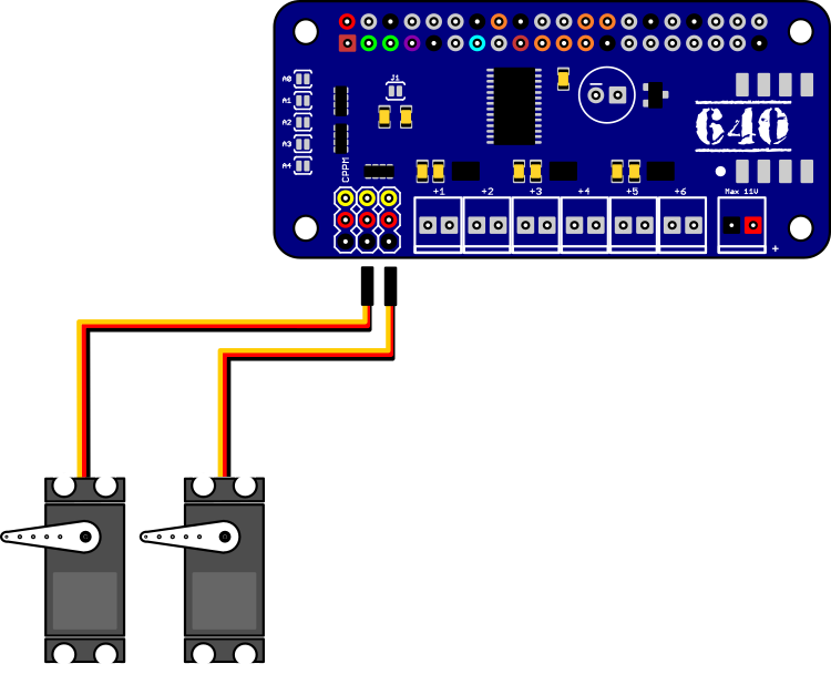
Connecting Servos
Servos can be connected to the two servo connections to the immediate left of the DC motor connections. The 640 is setup to provide power to the Servos from the Raspberry Pi’s 5v power. This can be changed to use the external power supply by modifying the solder header on the bottom of the board.
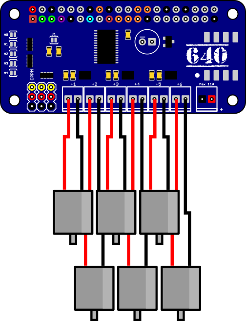
Connecting Motors
Motors are connected to each individual motor connector on the board. You should try to wire each motor up with the positive and negative wires on the same sides as all the others - unless you know that a particular motor (or set of motors) is reversed on your robot.
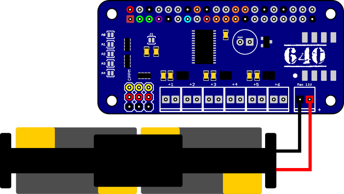
Connecting the power
The power supply for your motors is connected to the connector on the far right of the board. The 640 board can take between 2V and 11V for the motor power supply. It motor power supply is kept apart from the Raspberry Pi supply so that any voltage drop caused by the motors doesn’t damage your Raspberry Pi or cause it to reboot.
There is a polarity protection mosfet on the 640 board to protect the motor drivers, so if you find that your motors aren’t moving, then check that you have the battery connected the right way around.
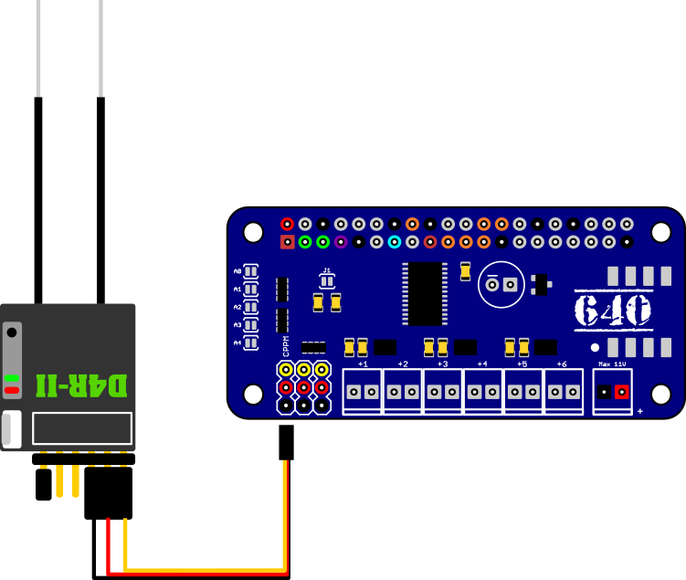
Connecting your RC receiver
The RC receiver is connected to the 3-pin connector on the far left of the board. Your Radio Control (RC) receiver should be capable of outputting CPPM or PPM-SUM signals. For some RC receivers need a jumper placed across two pins in order to enable this mode (as is the case with the D4R-II receiver displayed).
Once you have your RC receiver connected to the board and bound (linked) to yur RC transmitter, you should run the C++ PPM decoder example code (below) to make sure that the signals are being received correctly.
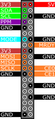
640 Pinout
The pins used by the 640 board are shown in the diagram below. All GND pins are linked so have all been marked.
Programming the 640
Installing the Python libraries
The Python libraries for the 640 board and some example scripts are available via our GitHub repository. To install them open a terminal window on your Raspberry Pi (unless you are running with only the command line) and enter the following:
$ git clone https://github.com/darkwaterio/darkwater_python_640.gitNext you need to navigate into the new directory so enter:
$ cd ./darkwater_python_640And once in there we can install the libraries with:
$ sudo python setup.py installExample scripts
Once everything is installed we can have a play with the example scripts included in the download. As well as being useful to test each part of your board, they are also handy as a starting point when writing your own scrips.
Let’s move into the examples directory and take a look at what is there.
$ cd ./examplesIf you list the files in this directory, you should see a few test scripts
$ ls -al640motortest.py
This script will start each motor port, in the forwards direction, in turn from left to right and then do the same backwards. To run the script enter the following:
$ python 640motortest.py640servotest.py
This script will move any servos connected to the servo headers left, then center, then right. To run the script enter the following:
$ python 640servotest.py640steppertest.py
This script divides the 6 motor ports into 3 stepper motor ports. Motor 1 and 2 will be stepper 1, motor 3 and 4 will be stepper 2 and motor 5 and 6 will be stepper 3.
Each stepper will be moved forwards and backwards through 400 steps when the test script is run:
$ python 640steppertest.pyThe Python API
Now you know everything works, it’s time to write your own scripts. So create a new python script in your editor with a memorable name and add the following lines to import our libraries:
import time
from darkwater_640 import dw_Controller, dw_Motor, dw_Servo, dw_Stepper
Create a controller
The dw_controller object controls access to all the elements on the 640 board, so the first thing we need to do is create a controller - we pass in the address of the 640 board as a parameter - the default address is 0x60
dw = dw_Controller( addr=0x60 )Now that we have the controller created, we can access all the connectors on the board.
Select a Motor
There are 6 motor ports on the 640 board numbered 1 to 6 from left to right (with the ports facing you ).
If we want to control a motor on port number 1 then we need to request the motor object for that port from our controller - this is very easily done with a single line
m1 = dw.getMotor(1)Motor driving
There are two main commands that you can give a motor - to move in a direction and to stop.
We’ll start with the main command to stop the motor
off()
The off command will switch off the motor and apply the brakes
m1.off()setMotorSpeed( speed )
We can also stop the motor by using the second command and passing a speed of 0
m1.setMotorSpeed(0)The setMotorSpeed command allows you to specify the speed of each motor - there are two different speed ranges the first goes from -255 to 255, the second from 1000 to 2000.
If you are familiar with radio control vehicles and ESC motors then you will recognise the second range.
For now we’ll concentrate on the first range.
To get your motor going forwards at full speed you should set its speed at 255
m1.setMotorSpeed(255)To get your motor going backwards at full speed you should set its speed to -255
m1.setMotorSpeed(-255)The numbers from 0 to the maximum in each direction will drive the motor at a slower speed, so for half speed forwards we’d use
m1.setMotorSpeed(125)And for a slow speed backwards we can use
m1.setMotorSpeed(-50)Alternate speed range
If you plan to move from a DC driven robot to an ESC motor powered robot then it makes sense to use the same conventions that will work on both, so you can also use the 1000 to 2000 speed range with the 640 board
To get your motor going forwards at full speed you should set its speed to 2000
m1.setMotorSpeed(2000)For full speed reverse you should set the speed to 1000
m1.setMotorSpeed(1000)And to stop the motor we can set the speed to the mid point which is 1500
m1.setMotorSpeed(1500)As before, any number between 1500 and the maximum in each direction will drive the motor at a slower speed, so for half speed forward you’d set the speed to 1750
m1.setMotorSpeed(1750)and half speed in revers would be 1250
m1.setMotorSpeed(1250)Select a Servo
There are two servo ports on the 640 board. They are numbered 1 and 2 with number 1 to the left hand side and number 2 the closest to the motor ports.
You select a servo in the same manner as you select motors, by requesting a servo object from the controller - to select the first servo we use:
s1 = dw.getServo(1)Servo control
Once you have a servo object there are currently three commands you can run.
off()
The off command will switch off your servo and stop any signals being sent to it.
s1.off()setPWMuS( microseconds )
This command will allow you to set the PWM pulse to the Servo in microseconds.
Most standard servos use a parameter value of 1000 for fully counter-clockwise, 2000 for fully clockwise, and 1500 for the middle - though you may have a wider range on your servo, so you should check the technical documentation for it to get the finer details.
s1.setPWMuS(1500) # middle
s1.setPWMuS(2000) # fully clockwise
s1.setPWMuS(1000) # fully counter clockwise
setPWMmS( milliseconds )
This command allows you to specify the PWM pulse in milliseconds rather than seconds.
s1.setPWMmS(1.5) # middle
s1.setPWMmS(2.0) # fully clockwise
s1.setPWMmS(1.0) # fully counter clockwise
Select a Stepper motor
You can control up to 3 stepper motors with the 640 board - each stepper motor uses two motor ports for 4 wire stepper motors and three motor ports for 5 wire stepper motors.
Running 5 wire stepper motors is almost the same as 4 wire stepper motos but requires a small extra step which we’ll explain at the end.
Each stepper motor is assigned to a pair of motor ports -
- Stepper motor 1 - uses motor ports 1 and 2
- Stepper motor 2 - uses motor ports 3 and 4
- Stepper motor 3 - uses motor ports 5 and 6
The first step is to identify the two wires for each coil on your stepper motor (you may need to read the technical documentation for your motor to find this out) and attach these two wires to each port.
Example: You have a stepper motor with 4 wires - orange, pink, yellow and blue. If the orange and pink wires for your stepper motor are attached to coil one then attach these wires to motor port 1, attach the two remaining wires to motor port 2.
Once you have your stepper motor wired up you need to request the relevant stepper motor object from the controller.
stepper1 = dw.getStepper(1)Stepper motor control
There are four commands for stepper motors. The first one you’ll recognise
off()
The off command will switch off the stepper motor
stepper1.off()setMotorSpeed( rpm )
This command allows you to set the speed of your stepper motor. Pass the number of revolutions per minute that you want your stepper motor to run at.
stepper1.setMotorSpeed(200)oneStep( direction, style )
This command will move the stepper motor one step in your chosen direction -
- dw_Controller.FORWARD - set the stepper motor to move forward
- dw_Controller.REVERSE - set the stepper motor to move backwards
There are two stepping styles available -
- dw_Controller.SINGLE - this is the simplest method of stepping which activates a single coil at a time to move and hold the motor. This method uses the least amount of power.
- dw_Controller.DOUBLE - this is a slightly more complex method of stepping which uses to coils to move and hold the motor. This method uses twice as much power as the single step, but is more powerful.
stepper1.oneStep(dw_Controller.FORWARD, dw_Controller.SINGLE)
stepper1.oneStep(dw_Controller.REVERSE, dw_Controller.DOUBLE)
step( steps, direction, style )
If you want to move the stepper motor a set number of steps then you can use this command. This, however, will stop all processing until the motor has moved the specified number of steps.
stepper1.step(200, dw_Controller.FORWARD, dw_Controller.SINGLE)
stepper1.step(200, dw_Controller.REVERSE, dw_Controller.DOUBLE)
If you want more control and need to move two or more motors at the same time then you should use the oneStep command.
Installing the C++ libraries
The C++ libraries for the 640 board and some example scripts are available via our GitHub repository. To install them open a terminal window on your Raspberry Pi (unless you are running with only the command line) and enter the following:
$ git clone https://github.com/darkwaterfoundation/darkwater_cplus_640.gitOnce they are download we can navigate into the new directory and take a look around - so enter:
$ cd ./darkwater_cplus_640Let’s list the contents of that new directory by typing
$ ls -alYou should see two directories (and a README.md file which contains this content), called darkwater and examples.
The darkwater directory contains all of the classes needed to control your board and the examples directory contains a selection of demo code we’ve put together to show you how they are used.
Examples
Take a look in the examples directory and you will see the following available demos.
Motor
The Motor example will start each motor in turn from 1 through to 6 in a forwards direction, then stop them and do the same in reverse. To build this demo type the following:
$ cd ./Motor
$ make
Once you are returned to the command prompt you can run the program with the command:
$ sudo ./MotorServo
The servo example will move each of the two servos on the 640 board backwards and forwards six times. To build this demo type the following:
$ cd ./Servo
$ make
Once it is compiled you can run it with the command:
$ sudo ./ServoPPM
The PPM example will read the input from a PPM radio control receiver connected to the CPPM header on the 640 board, interpret the first 6 channels and move the corresponding motors.
To build this demo type the following:
$ cd ./PPM
$ make
Once compiled, attach your CPPM receiver to the CPPM connector (see here CPPM set up) and run the program - you will see the output for each channel on the screen as it runs. Attaching motors to each of the motor connectors will allow you to control them individually by moving the sticks on your RC transmitter.
$ sudo ./PPMAccelGyroMag
If you have a 9DoF expansion board on your 640 board or are using a SOAR board then this example will read and output the Gyroscope, Accelerometer and Compass readings.
To compile and run it, type the following
$ cd ./AccelGyroMag
$ make
$ sudo ./AccelGyroMag
The C++ API
If you take a look at the code in each of the examples you should be able to get an idea of how the 640 board API works. We’ll go into more detail of each of the available commands below.
The first thing we need to do for our program is to import the required libraries - so near the top of your new program you will put
#include "darkwater/DW640.h"
#include "darkwater/Util.h"
#include <stdlib.h>
If you will be using the CPPM header for input then you will also need to add:
#include <pigpio.h>
#include <stdio.h>
#include <unistd.h>
For this example, we’ll include everthing in a main function for neatness - have a look at the PPM example code for an alternate set up.
int main()
{

}
Create a controller
The DW640 object controls access to all the elements on the 640 board, so the first thing we need to do is create a controller - we pass in the address of the 640 board as a parameter - the default address is 0x60 so if you haven’t changed the address then you can leave this out.
DW640 dw(0x60);
dw.initialize();
Now that we have the controller created, we can access all the connectors on the board.
Select a Motor
There are 6 motor ports on the 640 board numbered 1 to 6 from left to right (with the ports facing you ).
If we want to control a motor on port number 1 then we need to request the motor object for that port from our controller - this is very easily done with a single line
DW_Motor *dw1 = dw.getMotor(1);Motor driving
There are two main commands that you can give a motor - to move in a direction and to stop.
We’ll start with the main command to stop the motor
off()
The off command will switch off the motor
dw1->off()setMotorSpeed( speed )
We can also stop the motor by using the second command and passing a speed of 0
dw1->setMotorSpeed(0);The setMotorSpeed command allows you to specify the speed of each motor - there are two different speed ranges the first goes from -255 to 255, the second from 1000 to 2000.
If you are familiar with radio control vehicles and ESC motors then you will recognise the second range.
For now we’ll concentrate on the first range.
To get your motor going forwards at full speed you should set its speed at 255
dw1->setMotorSpeed(255);To get your motor going backwards at full speed you should set its speed to -255
dw1->setMotorSpeed(-255)The numbers from 0 to the maximum in each direction will drive the motor at a slower speed, so for half speed forwards we’d use
dw1->setMotorSpeed(125)And for a slow speed backwards we can use
dw1->setMotorSpeed(-50)Alternate speed range
The spped range above is easy to use as you can quickly see what speed is forwards, backwards and stopped. ESC powered motors use a different range that goes from 1000 to 2000, with 1500 (the middle point) being stop.
Both the ESCAPE and 640 boards can use either range, but if you are primarily working with ESC powered motors and Radio Control inputs then you should use this range as it makes programming a lot easier.
To get your motor going forwards at full speed you should set its speed to 2000
dw1->setMotorSpeed(2000)For full speed reverse you should set the speed to 1000
dw1->setMotorSpeed(1000)And to stop the motor we can set the speed to the mid point which is 1500
dw1->setMotorSpeed(1500)As before, any number between 1500 and the maximum in each direction will drive the motor at a slower speed, so for half speed forward you’d set the speed to 1750
dw1->setMotorSpeed(1750)and half speed in reverse would be 1250
dw1->setMotorSpeed(1250)Select a Servo
There are two servo ports on the 640 board. They are numbered from 1 and 2 with number 1 to the left hand side and number 2 the closest to the motor connectors.
You select a servo in the same manner as you select motors, by requesting a servo object from the controller - to select the first servo we use:
DW_Servo *s1 = dw.getServo(1);Servo control
Once you have a servo object there are currently three commands you can run.
off()
The off command will switch off your servo and stop any signals being sent to it.
s1->off();setPWMuS( microseconds )
This command will allow you to set the PWM pulse to the Servo in microseconds.
Most standard servos use a parameter value of 1000 for fully counter-clockwise, 2000 for fully clockwise, and 1500 for the middle - though you may have a wider range on your servo, so you should check the technical documentation for it to get the finer details.
s1->setPWMuS(1500); // middle
s1->setPWMuS(2000); // fully clockwise
s1->setPWMuS(1000); // fully counter clockwise
setPWMmS( milliseconds )
This command allows you to specify the PWM pulse in milliseconds rather than seconds.
s1->setPWMmS(1.5); // middle
s1->setPWMmS(2.0); // fully clockwise
s1->setPWMmS(1.0); // fully counter clockwise
Select a Stepper motor
You can control up to 3 stepper motors with the 640 board - each stepper motor uses two motor ports for 4 wire stepper motors and three motor ports for 5 wire stepper motors.
Running 5 wire stepper motors is almost the same as 4 wire stepper motors but requires a small extra step which we’ll explain at the end.
Each stepper motor is assigned to a pair of motor ports -
- Stepper motor 1 - uses motor ports 1 and 2
- Stepper motor 2 - uses motor ports 3 and 4
- Stepper motor 3 - uses motor ports 5 and 6
The first step is to identify the two wires for each coil on your stepper motor (you may need to read the technical documentation for your motor to find this out) and attach these two wires to each port.
Example: You have a stepper motor with 4 wires - orange, pink, yellow and blue. If the orange and pink wires for your stepper motor are attached to coil one then attach these wires to motor port 1, attach the two remaining wires to motor port 2.
Once you have your stepper motor wired up you need to request the relevant stepper motor object from the controller.
DW_Stepper *st1 = dw.getStepper(1);The default stepper object created assumes that your stepper motor has 48 steps per revolution - if you motor has more or less steps per revolution then you can specify this using an alterative command:
DW_Stepper *st1 = dw.getStepper(1, 48);Change the 48 in the line above to the number of steps your stepper motor has per revolution.
Stepper motor control
There are four commands for stepper motors. The first one you’ll recognise
off()
The off command will switch off the stepper motor
st1->off();setMotorSpeed( rpm )
This command allows you to set the speed of your stepper motor. Pass the number of revolutions per minute that you want your stepper motor to run at.
st1->setMotorSpeed(200);oneStep( direction, style )
This command will move the stepper motor one step in your chosen direction -
- DW_FORWARD - set the stepper motor to move forward
- DW_REVERSE - set the stepper motor to move backwards
There are two stepping styles available -
- DW_SINGLE - this is the simplest method of stepping which activates a single coil at a time to move and hold the motor. This method uses the least amount of power.
- DW_DOUBLE - this is a slightly more complex method of stepping which uses to coils to move and hold the motor. This method uses twice as much power as the single step, but is more powerful.
st1->oneStep(DW_FORWARD, DW_SINGLE);
st1->oneStep(DW_REVERSE, DW_DOUBLE);
step( steps, direction, style )
If you want to move the stepper motor a set number of steps then you can use this command. This, however, will stop all processing until the motor has moved the specified number of steps.
st1->step( 400, DW_FORWARD, DW_SINGLE );
st1->step( 400, DW_REVERSE, DW_DOUBLE );
If you want more control and need to move two or more motors at the same time then you should use the oneStep command.
Compiling your code
Unlike with Python, we need to take an extra step with C++ and compile our code so that it can be run on the Raspberry Pi.
To do that, and to make it easier to re-compile as you update, we will create a makefile. The makefile is a little script that knows the location of all the libraries we want to include in our program and knows how to compile them together to make a single exectuable.